Goal
The goal of this project is to build and program a device to make two height adjustable desks move simultaneously with one interface. The two electric frames have to always be at the same height. I’m doing this project for my brother because he plans to weld two of those desk frames together for extra stability and lifting capacity.
The electric height-adjustable desk frames are from Xantron, which has it’s origin in Switzerland.
Teardown
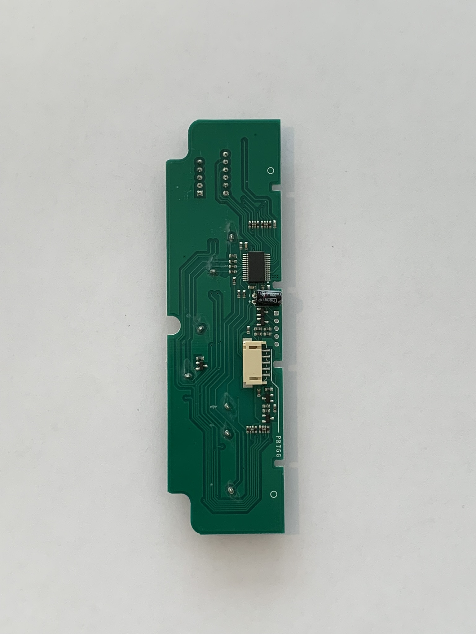
Controller
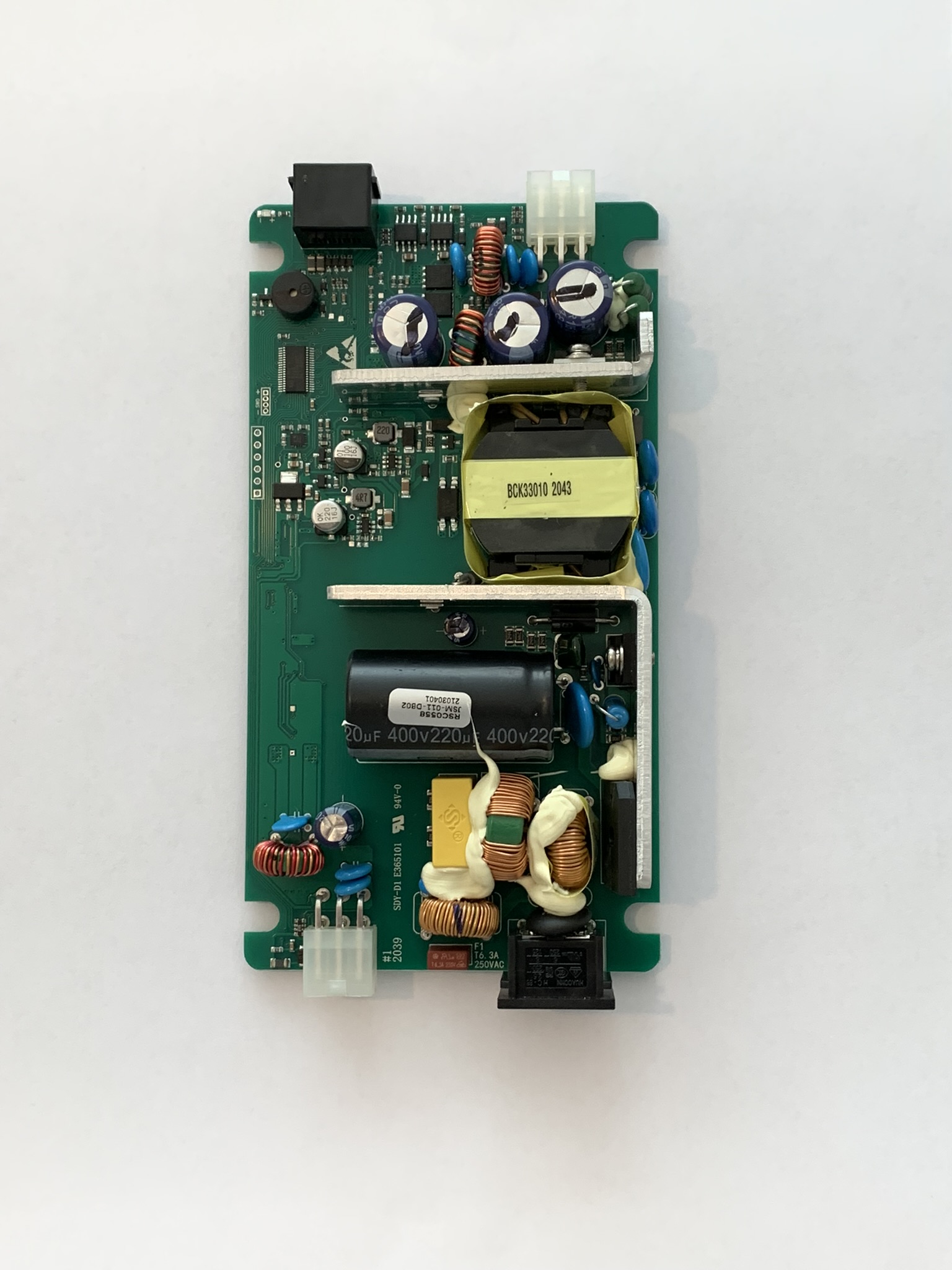
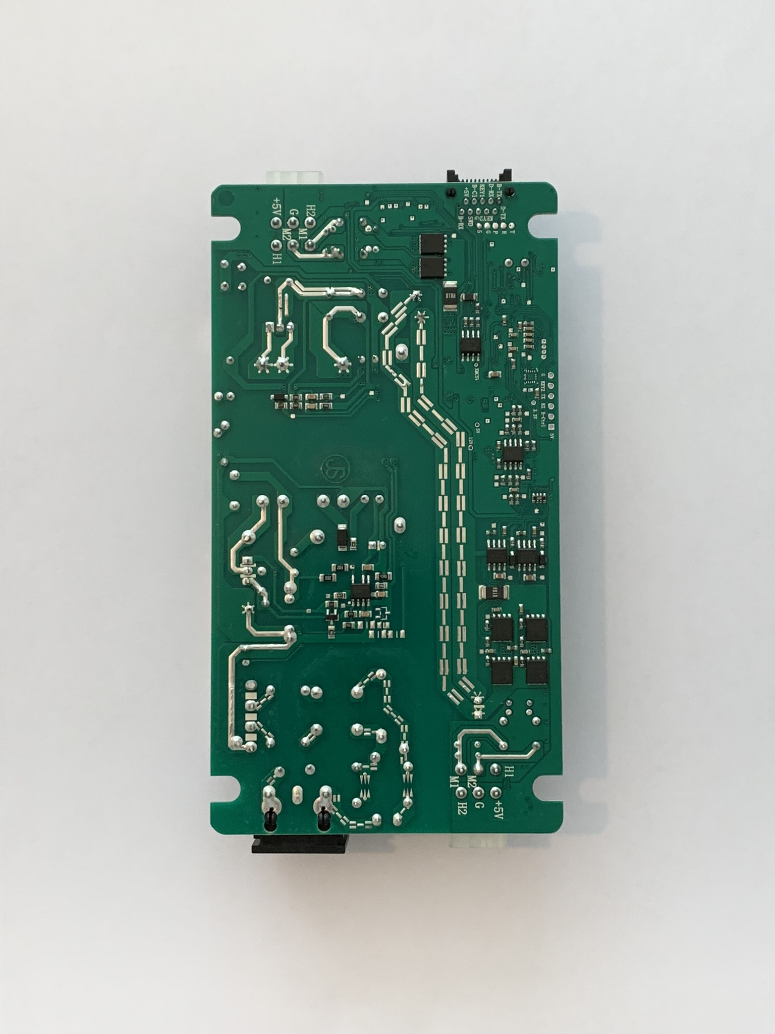
The controller consists a power supply, motor MOSFETs, a microcontroller and more.
Interface
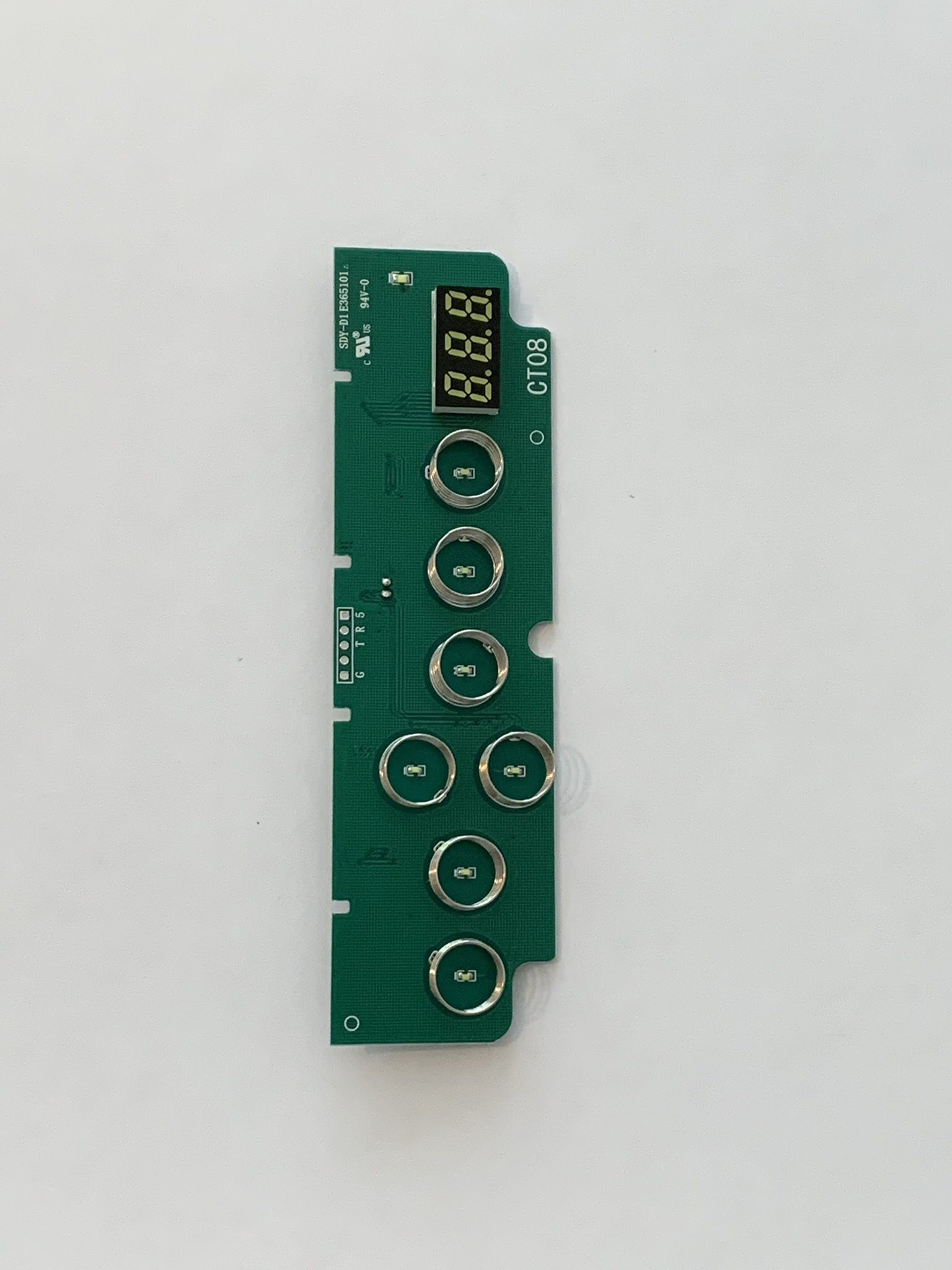
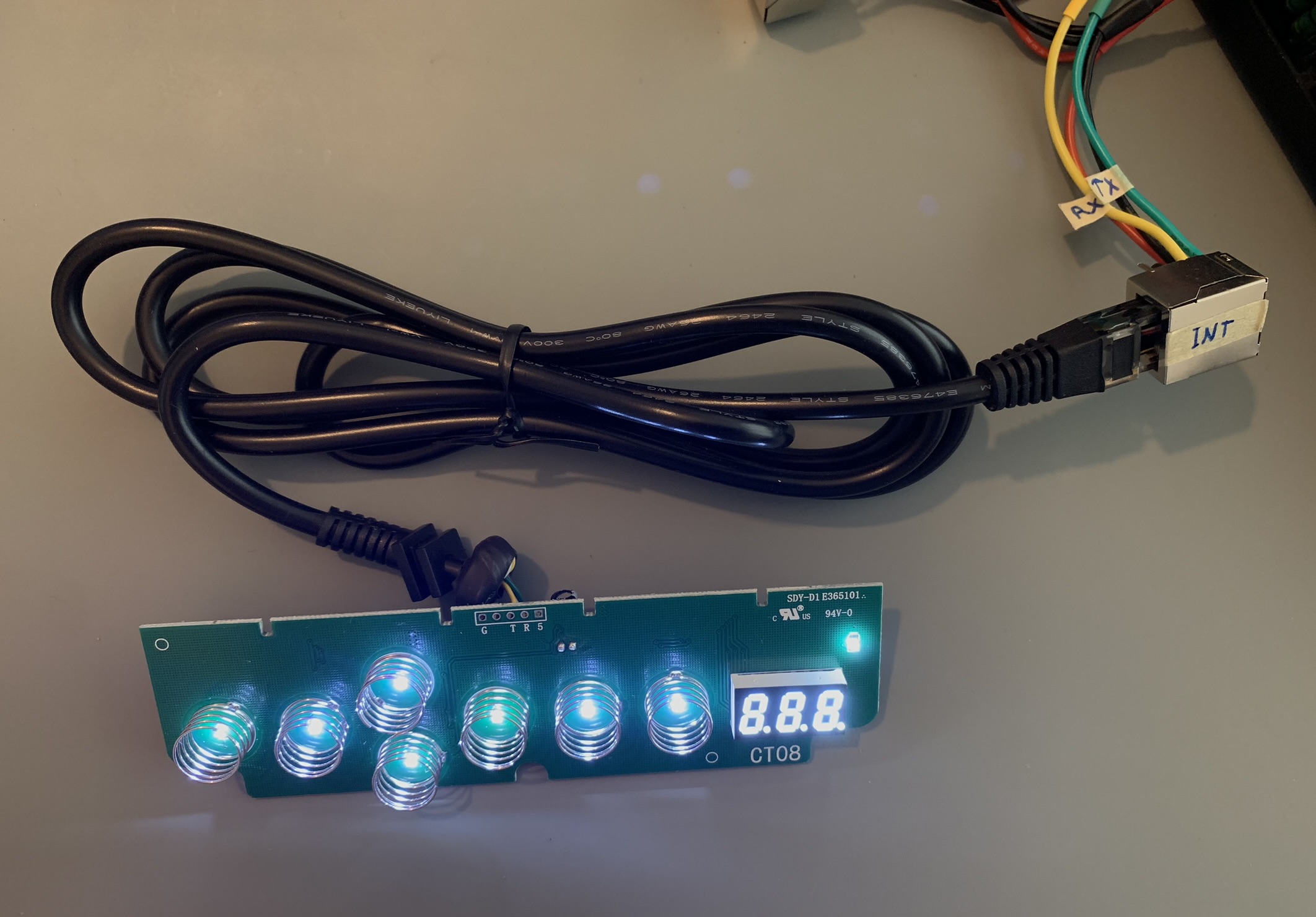
There are seven buttons and a 3 digit 7-segment display on the interface.
Leg Motor
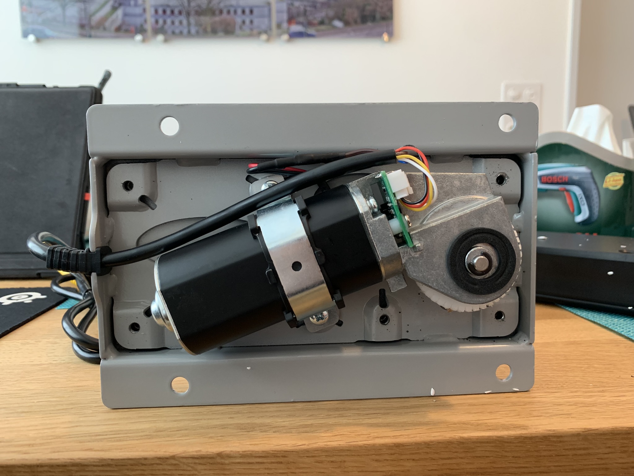
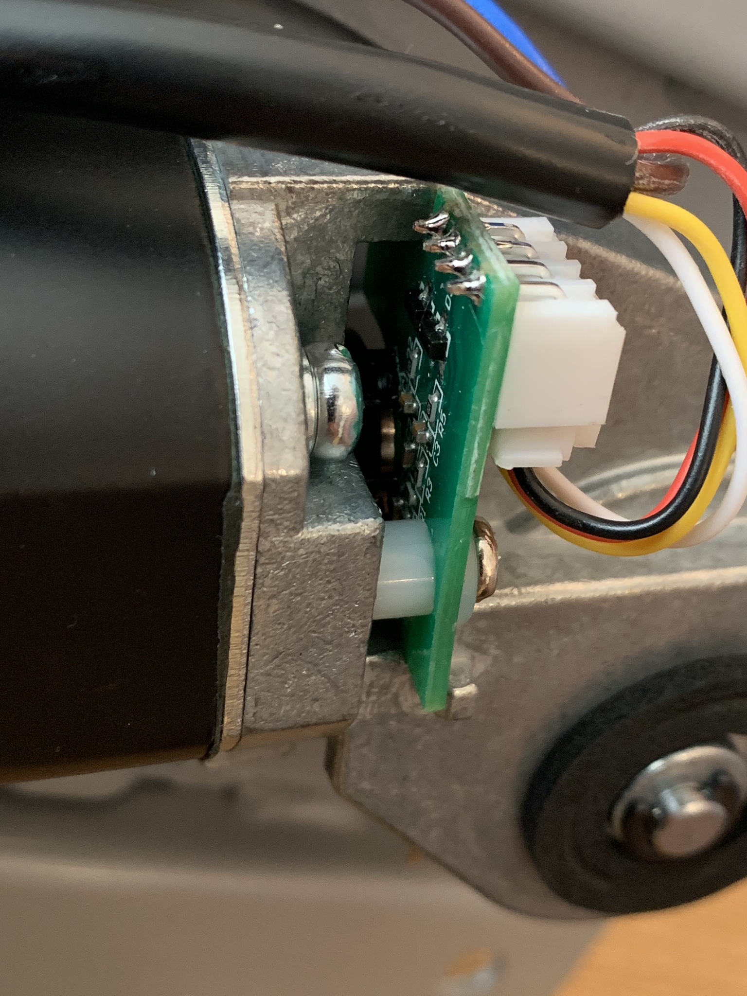
The leg is raised and lowered by the motor through a gearbox. The controller switches the motors and reads their angle through a Hall effect sensor.
Reverse-engineering the Protocol
-
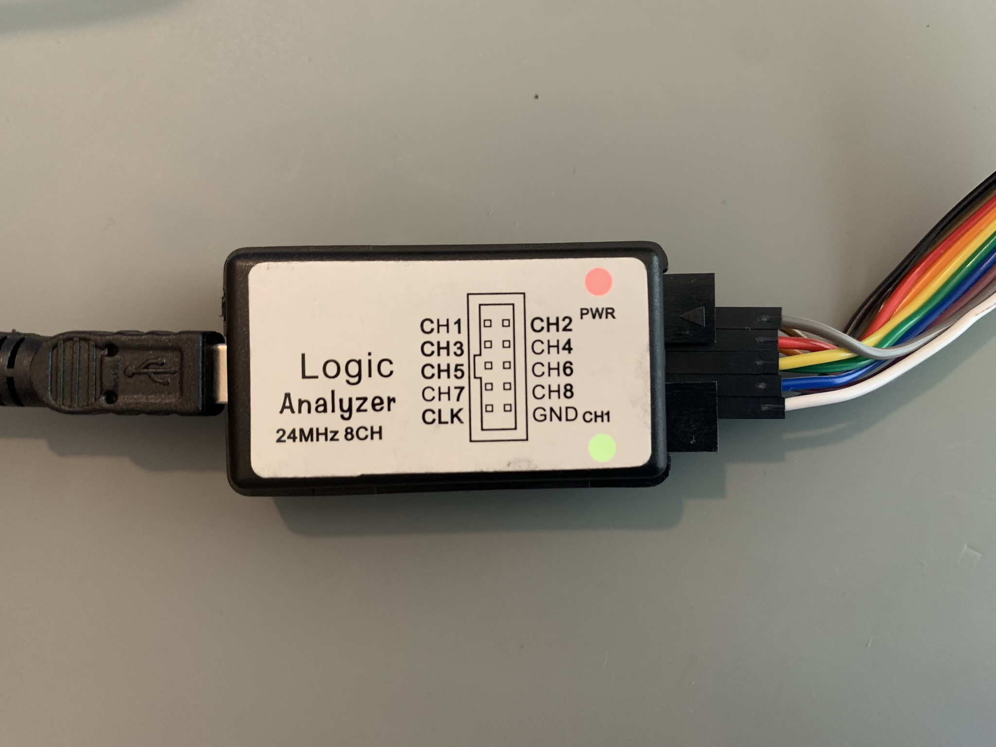
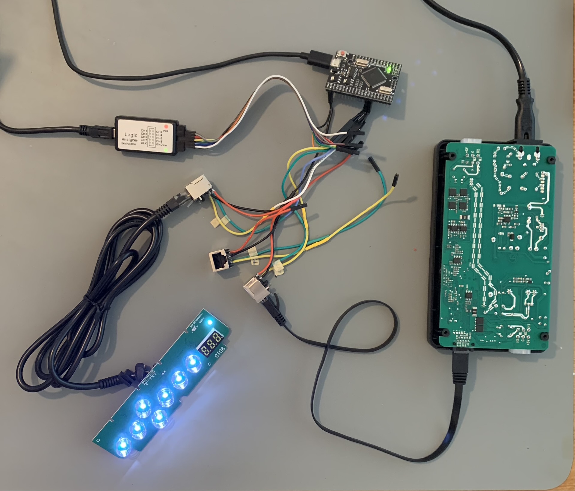
A logic analyzer is highly recommended because it makes this way easier. I’m using this device.
-
I connected the interface to the Arduino and logic analyzer using a RJ45 connector.
-
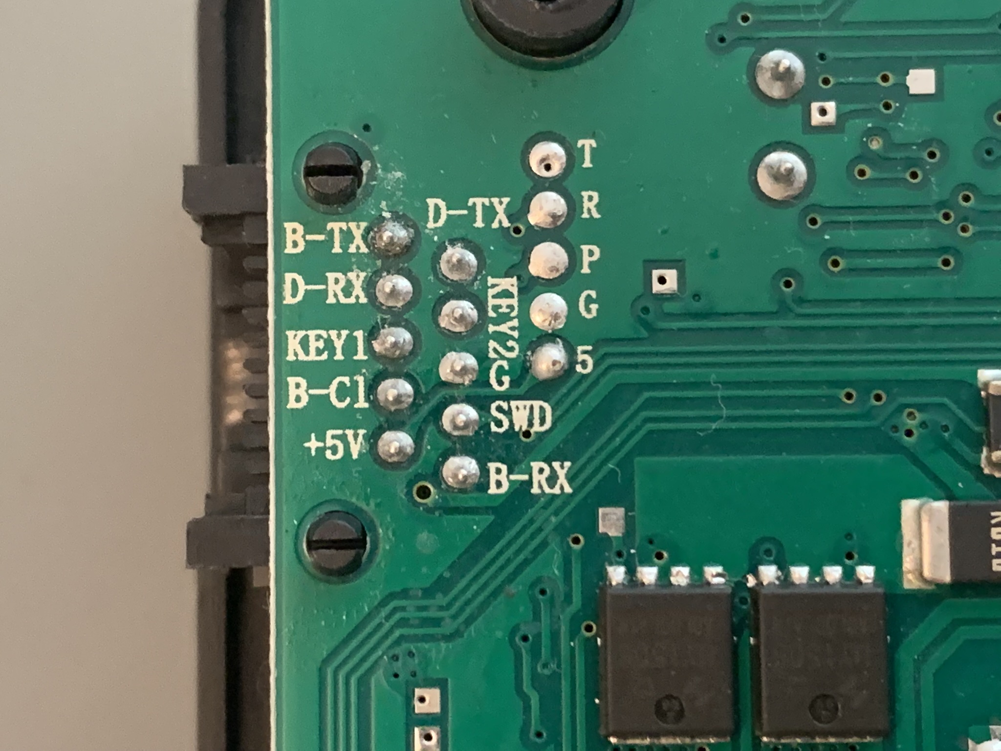
Thanks for leaving the pinout on the silkscreen. ;) Unfortunately, I couldn’t figure out what KEY1 and KEY2 stands for.
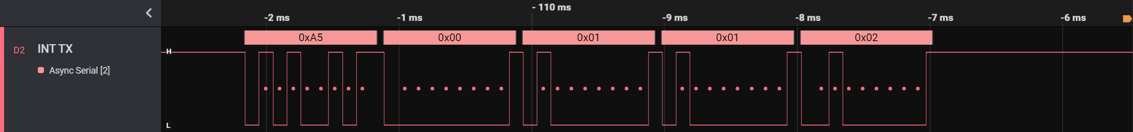
While no buttons are pressed
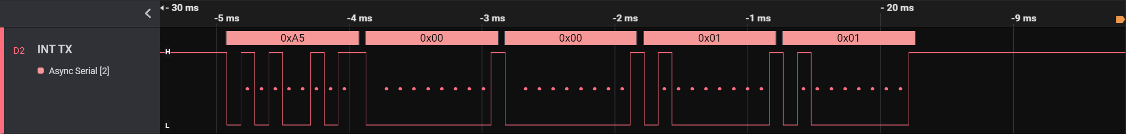
This is the serial data which the interface sends to the controller about every 12ms. I’m using the Saleae Logic software to analyze the signal.
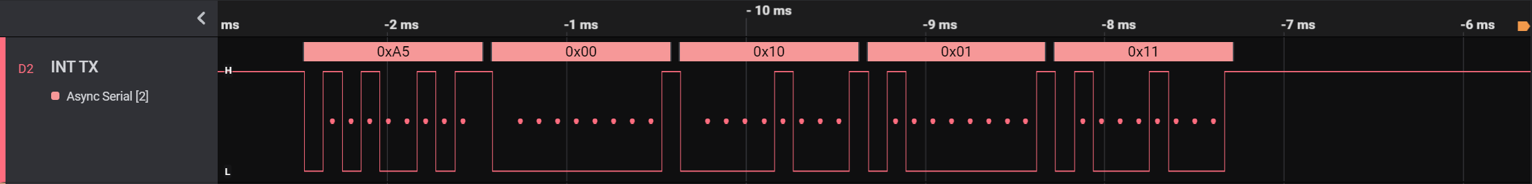
While the M button is pressed
This is the data sent while pressing the M button. Notice the third and the fifth byte changed. The value of the third byte (hex 0x01) corresponds to binary 0000001.
While the T button is pressed
This is the data sent while pressing the T button. Notice the third and the fifth byte changed. The value of the third byte (hex 0x10) corresponds to binary 0001000.
While the M and T buttons are pressed
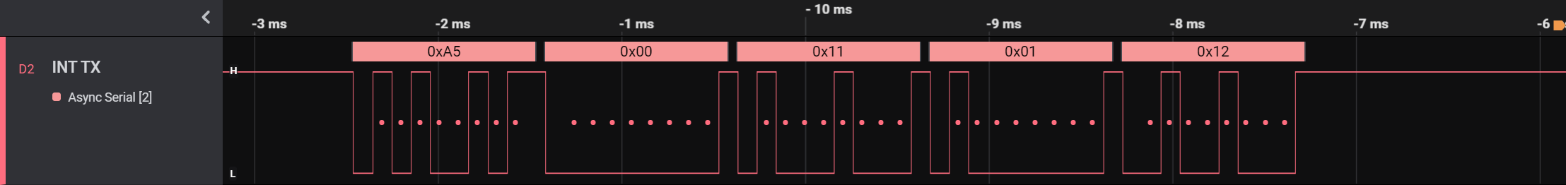
This is the data sent while pressing the M and T buttons. The value of the third byte (hex 0x11) corresponds to binary 0001001.
The fifth byte is most likely a checksum of every byte after the start byte (hex 0xA5).
After a bit of trying, I determined these bitmasks:
| Binary | Hex | Button |
|---|---|---|
| 00000001 | 0x01 | M |
| 00000010 | 0x02 | 1 |
| 00000100 | 0x04 | 2 |
| 00001000 | 0x08 | 3 |
| 00010000 | 0x10 | T |
| 00100000 | 0x20 | UP |
| 01000000 | 0x40 | DOWN |
Sending commands
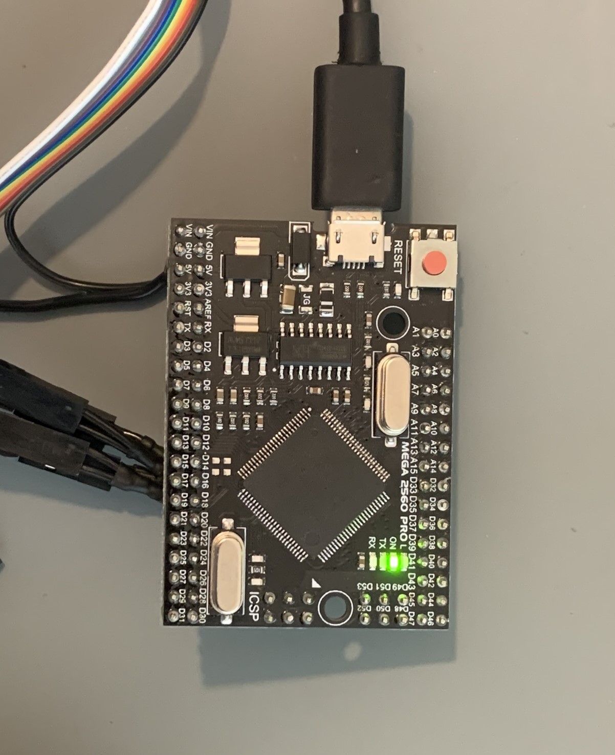
Connecting to the Arduino
-
The interface and controller are now connected to the Arduino’s serial ports.
-
I’m using an Arduino Mega 2650 Pro Mini.
Receiving, validating and handling Commands
Calculating Checksums
uint8_t checkSum(uint8_t *cmdBytes, uint8_t cmdLen)
{
  uint16_t sum = 0;
  for (int i = 1; i < cmdLen - 1; i++)
    sum += cmdBytes[i];
  return (sum % (0xFF + 1));
}
Receiving and handling Commands
void receiveCmd(uint8_t from, uint8_t cmdLen)
{
  HardwareSerial *inputSerial = getSerial(from);
  while ((*inputSerial).available() > 0)
  {
    uint8_t byte = (*inputSerial).peek();
    if (byte != (isCtrlSerial(from) ? PROT_INT_START : PROT_CTRL_START))
    {
      (*inputSerial).read();
      continue;
    }

    uint8_t *cmdBytes = new uint8_t[cmdLen];
    (*inputSerial).readBytes(cmdBytes, cmdLen);
    if (cmdBytes[cmdLen - 1] == checkSum(cmdBytes, cmdLen))
    {
      handleCmd(from, cmdBytes, cmdLen);
      return;
    }
  }
}
This C++ snippet receives and checks commands and calls the handler function if a command is received. You can find all this project’s code on this GitHub repository.
Sending Commands
struct intButtons
{
  bool pressedM;
  bool pressed1;
  bool pressed2;
  bool pressed3;
  bool pressedT;
  bool pressedUP;
  bool pressedDW;
};

void sendCtrlCmd01(uint8_t to, intButtons buttonStates)
{
  uint8_t state = 0;
  if (buttonStates.pressedM)
    state += PROT_CMD_CTRL_BUTTON_M;
  if (buttonStates.pressed1)
    state += PROT_CMD_CTRL_BUTTON_1;
  if (buttonStates.pressed2)
    state += PROT_CMD_CTRL_BUTTON_2;
  if (buttonStates.pressed3)
    state += PROT_CMD_CTRL_BUTTON_3;
  if (buttonStates.pressedT)
    state += PROT_CMD_CTRL_BUTTON_T;
  if (buttonStates.pressedUP)
    state += PROT_CMD_CTRL_BUTTON_UP;
  if (buttonStates.pressedDW)
    state += PROT_CMD_CTRL_BUTTON_DW;

  uint8_t cmdBytes[5] = {PROT_CTRL_START, 0x00, state, PROT_CMD_CTRL_BUTTONS};
  cmdBytes[4] = checkSum(cmdBytes, 5);
  sendCmd(to, cmdBytes, 5);
}
This function assembles and sends the command of which buttons are pressed to the controller.
Controller’s Response
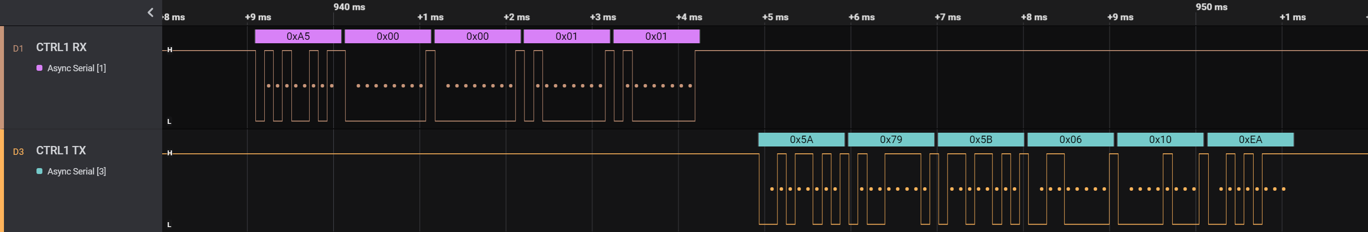
You can see the command my code sent at the brown line. The orange line is the controller sending a response. I suspect the response contains which segment on the three 7-segment displays should light up.
Note that the data coming from the controller starts with 0x5A and not 0xA5 which is sent when a command from the interface is sent.
Playing back a Command to the Interface manually
void sendIntCmd10(uint8_t to)
{
  uint8_t cmdBytes[6] = {PROT_INT_START, B01111001, B01011011, B00000110, PROT_CMD_INT_STATE};
  cmdBytes[5] = checkSum(cmdBytes, 6);
  sendCmd(to, cmdBytes, 6);
}
This function sends a command which the controller normally sends to the interface, which must be after a status update sent by the interface. I’m not certain of the parameters of this command yet so I’m just using the values which I saw in the analyzer.
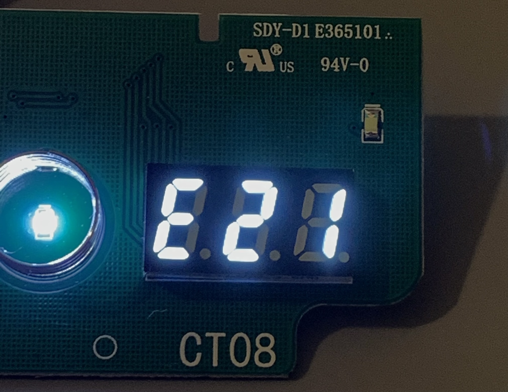
Just as hoped, the interface now displays the same thing displayed at the time I took the data. Hooray!
Parameters
To figure out what the parameters do, I’m going to try to change them slightly:
// uint8_t cmdBytes[6] = {PROT_INT_START, B01111001, B01011011, B00000110, PROT_CMD_INT_STATE};
   uint8_t cmdBytes[6] = {PROT_INT_START, B01110110, B10110000, B00000000, PROT_CMD_INT_STATE};
Which results to HI.
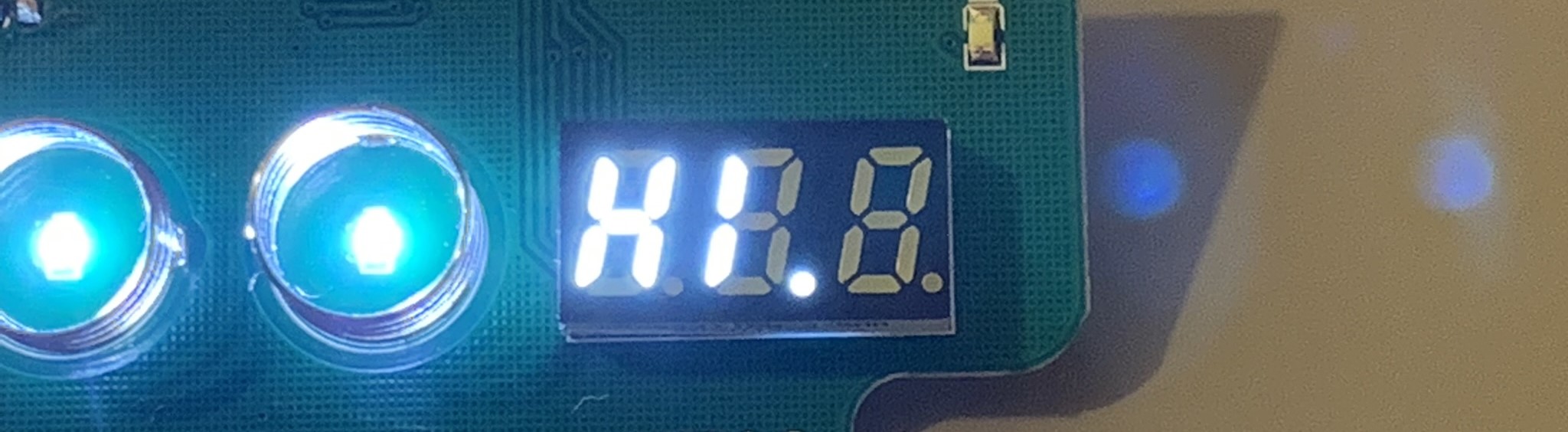
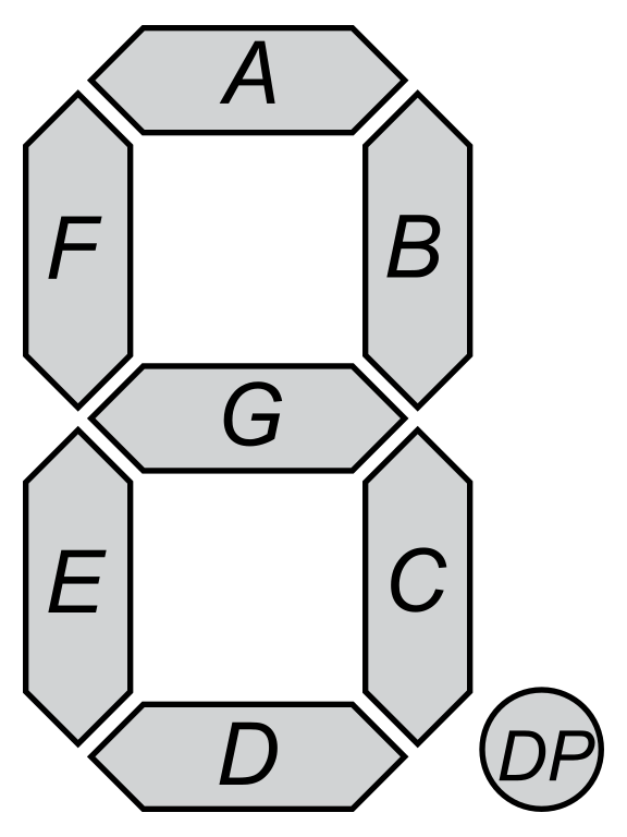
Nice! The first parameter byte defines the first digit, the second parameter byte the second digit, etc.. The least significant bit in each byte sets the segment A, the bit before that the segment B, etc.. The most significant bit sets the dot. For some reason, the display will not display if all the bits are set.
Here I’ve made a table of the bits corresponding to their segment:
| Binary | Hex | Segment |
|---|---|---|
00000001 |
0x01 |
A |
00000010 |
0x02 |
B |
00000100 |
0x04 |
C |
00001000 |
0x08 |
D |
00010000 |
0x10 |
E |
00100000 |
0x20 |
F |
01000000 |
0x40 |
G |
10000000 |
0x80 |
DP |